In modern technology and the increased demand for high-performance materials in various industries, such as Aerospace, Communications, and Semiconductors,
have led to the use of new materials like CFRP, MMC, CMC, Green Ceramics, Sintered Ceramics, and others.
These materials offer various advantages over traditional materials like metal alloys, such as high strength-to-weight ratio, good electrical and thermal conductivity, and improved durability. However, machining these materials is a challenging task, as they are brittle and prone to cracking, leading to increased tool wear and reduced machining efficiency.
CFRP is used extensively in Aerospace industry to achieve high strength to weight ratio.
CMC (Ceramic Matrix Composite) is used in modern jet engine to produce the heat zone blades improving jet engine efficiency.
Brake disks in modern and sport vehicles are made from MMC (Metal Matrix Composites), in this case, Aluminum matrix with SiC hard particles.
Cell phones enclosures and other communication equip. enclosures are made from Aluminum with high (>8%) Silicon content to achieve strength and durability.
In the semiconductors industry, ceramics like c-Si is used for showerhead parts, SiC is used for cooling elements and Quartz is use as furnace tubes.
In nuclear applications, the use of AlB2 and B4C, is common as a neutron absorber and fuel rods cladding.
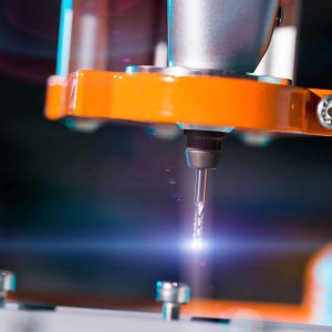
PCD (Polycrystalline Diamond) cutting tools have emerged as a solution to these challenges and offer several benefits in the machining of these advanced materials.
PCD cutting tools are made of a diamond layer that is sintered to a carbide substrate, creating a cutting edge that is extremely hard, durable, and abrasive resistant. This makes PCD cutting tools ideal for machining materials like CFRP, MMC, CMC, Ceramics, and nonferrous alloys.
One of the main benefits of using PCD cutting tools in these materials is their ability to achieve high precision and accuracy. The hard and durable cutting edge of PCD tools ensures that the cuts are smooth, reducing the need for secondary operations, and leading to improved dimensional accuracy. This is particularly important in the Aerospace industry, where high precision components are required for complex assemblies and aerospace systems.
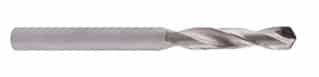
PCD Drill commonly used in Aerospace in CFRP and GFRP applications.
Another advantage of using PCD cutting tools is the reduced tool wear. The cutting edge of PCD tools is made of diamond, which is the hardest materials known to man. This means that the cutting edge is highly resistant to abrasion and wear, resulting in longer tool life compared to conventional cutting tools. This translates to reduced downtime for tool replacement, increased machining efficiency, and cost savings.
Drill life comparison in CFRP application between PCD and Tungsten carbide drills. Life difference is almost x20
In the Communications and Semiconductors industries, high surface finish is critical for ensuring optimal performance and reliability of the components. PCD cutting tools can achieve high surface finishes due to their fine grain structure, leading to improved surface quality, and reduced roughness. This is particularly important for semiconductors, where the surface finish affects the performance and reliability of the devices. In addition, semiconductors materials, such as single crystal silicon, Alumina, SiC and Quartz, are extremely hard materials, where only PCD tools can be used with reasonable longevity.
\
PCD micro-Drill 0.75mm used in Semiconductors, in Single Crystal Silicon showerhead plates drilling.
PCD Multi-flute endmill 2.0mm for machining Hard SiC and TC
PCD 3 FL Spiral endmill 1/4″ for machining green Ceramics and Al-Si enclosures for communication Ind.
In conclusion – PCD cutting tools offer numerous benefits in the machining of advanced materials like CFRP, MMC, CMC, green ceramics, sintered ceramics, etc. They provide high precision, accuracy, and surface finish, while also reducing tool wear and increasing machining efficiency. These benefits make PCD cutting tools a valuable tool in the Aerospace, Communications, and Semiconductors industries, and they are likely to play an increasingly important role in these industries as the demand for advanced materials continues to grow.
Some of you, who are in the aerospace industry, are probably familiar with a drill/countersink tool used in CNC manufacturing, to machine both the hole and the chamfer for the rivet head.
Did you know that with some modification, the same concept works also in manual operations? We’re here to tell you about it.
What is a Drill/Countersink tool?
A Drill/Countersink is a tool used mostly in CNC manufacturing of aerospace parts, with a purpose to machine both the required hole diameter and the relevant chamfer size for the rivet head. The tool can be made from PCD or CVD to be used for Composites. The drill head can be made from carbide and the countersink from PCD, to handle stack materials, such as C/Al or C/Ti.
The usage of a Drill/CSK sometimes limited in CNC from various reasons:
It is not worthwhile preparing a jig for every part and machine it in CNC.
In some cases, the drill entrance side, is not the same side the chamfer has to be made.
When large part is about, there are concerns that along the part, you can not achieve the same chamfer size, due to minor part deflections in machining. In this case, drilling is done in CNC and countersinking later in manual operation at the assembly line.
While these circumstances limit the use of Drill/CSK in CNC, in assembly line, when all operations are done manually, the use of such a tools, does not exist so far.
What is the new concept?
Telcon developed a new concept of manual use Drill/CSK tools, which include 3 types of tools. All of them can be used manually with a thread connection to a standard stop-cage.
Reducing number of operations – saving one or two operations and setups.
Saving hourly costs.
Reducing lead time of part manufacturing.
Improving part quality – hole-chamfer concentricity is improved since both operations are done with the same tool.
Case study 1 – Composites/Composites:
Need to connect two panels of CFRP, with a thickness of 2.5+3.5mm.
Final hole diameter is 4.5mm with countersink angle of 100°.
Current process steps
Improved process steps
Lower panel is drilled in CNC with 3.3mm pilot holes.
Lower panel is drilled in CNC with 3.3mm pilot holes.
Upper panel is temporarily glued to the lower panel
Upper panel is temporarily glued to the lower panel
A 3.3mm drill is manually used to drill 3.3mm holes also at the upper panel while the lower panel holes guide the way.
A stepped Drill/CSK (3.3/4.5/100°) series DKCC is manually used to create the final 4.5mm diameter and the 100° chamfer
A carbide 4.5mm drill is manually used to enlarge holes in both panels.
Riveting is used to connect both panels
A PCD countersink is manually used for the chamfer of 100°
Riveting is used to connect both panels
Summary: with the use of Drill/CSK, 2 operations and 2 setups were saved. In these parts there are 80 holes to drill. This means 2×80 = 160 times drilling operations. Practically, the customer is able finishing 6 parts a day instead of 4 parts with the previous process.
Case study 2 – Aluminum/Aluminum:
Need to connect two periphery panels of Aluminum, with a thickness of 1.6+1.8mm.
Final hole diameter is 4.0mm with countersink angle of 100°.
Current process steps
Improved process steps
Lower panel is drilled in CNC with 2.5mm pilot holes.
Lower panel is drilled in CNC with 2.5mm pilot holes.
Upper panel is temporarily glued to the lower panel
Upper panel is temporarily glued to the lower panel
A 2.5mm drill is manually used to drill 2.5mm holes also at the upper panel while the lower panel holes guide the way.
A Drill/CSK (4.0/100°) series DKCA is manually used to create the final 4.0mm diameter and the 100° chamfer
A carbide 4.0mm drill is manually used to enlarge holes in both panels.
Riveting is used to connect both panels
A PCD countersink is manually used for the chamfer of 100°
Riveting is used to connect both panels
Summary: with the use of Drill/CSK, 2 operations and 2 setups were saved. In these parts there are at least 900 holes to drill only with this diameter. This means 2×900 = 1800 times drilling operations. Practically, the customer is able finishing manual operations on one part in 3 days instead of 5 days with the previous process.
As part of the fabrication of dentures it is a common practice to bind yourself with one manufacturer for the Cad/Cam machine and get both the Dental blanks and the Dental Burs in one package, this package is supplied by the manufacturer and can be adequate.
However, in these packages hides a large loss for the dental lab, bringing both the price up and provides redundant elements that may not be needed as part of the package. Many dental labs are reluctant to move from the manufacturer options even if it is an inferior product to the existing options in the market.
Getting the Right Dental tool for the job
Dental milling tools are a great example for this, while the manufacturers mostly sell regular milling tools from solid carbide, in the market exist a vastly superior option: Telcon PCD Dental tools with much longer lifespan and the ability to keep the cutting edge for much longer periods and under heavy workload, reducing in inaccuracy caused by wear of the cutting edge by a large margin.
Using Telcon patented alternative tools in the Cad/Cam milling machine will get you up to X8 savings per crown compared to existing milling tools provided by the machine manufacturer, and that just in direct tooling costs, the number can radically increase when considering setup time and inaccuracy ratio.
Why Dental labs don’t change the dental burs they use today?
In many cases Labs are reluctant to swap the machine manufacturer as the milling tools supplier, this is caused due to two things:
Simplicity: it’s close to home, it’s easy and you already know the supplier…
Fear factor: will it annal my warranty? Will the new product fit in the machine?
It’s very easy to see why the Labs are reluctant to swap suppliers, however it’s also very easy to see why the swap is very lucrative! By saving the inherent costs in the process the lab can have more bang for the buck and save thousands of dollars each year.
Why use Telcon dental milling tools?
Telcon dental milling tools are the cream of the crop, the Patented unique tools provide up to X15 more crowns per tool then existing tungsten carbide tools. The tools are very durable and allow high speed processing of many crowns without losing the cutting edge or harming the crown accuracy. In addition, telcon tools are adapted to fit the chucks of Sirona, Amann Girrbach and Zirkonzahn Cad/Cam milling machine.
Telcon tools have a long history of success and performance in very demanding industries such as aerospace industry, Telcon has decided to use this expertise in the Dental milling tools industry to create a vastly superior product that can out preform the existing products in the market by a large margin.
Points:
Bur Usage:
Applicable materials: Zirconia and PMMA discs only.
Cooling conditions: Dry or wet.
Bur selection: Refer to machine manufacturer’s standards.
Cutting Conditions:
Preset in most CAD/CAM programs.
Use tables below if no presets exist.
Bur Information:
Table details dimensions, catalog numbers, and compatible machine types.
Table: Bur Dimensions and Cutting Conditions
Material
Bur Type
Diameter (mm)
RPM (Roughing)
RPM (Finishing)
Table Feed (mm/min)
Ap (mm)
Ae (mm)
Zirconia
Tungsten Carbide
2.5
28,000
–
1200-1500
0.3
1.25
2.0
35,000
–
1200-1500
0.3
1.0
1.0
–
38,000
800-1000
0.1
0.1
0.6
–
63,000
500-600
0.05
0.05
0.5
–
64,000
500-600
0.05
0.05
CVD Diamond
2.5
28,000
–
1200-1500
–
–
SDT Diamond
2.5
28,000
–
1200-1500
–
–
PMMA
Tungsten Carbide
2.5
32,000
–
1300-1600
0.3
1.25
2.0
40,000
–
1300-1600
0.3
1.0
1.0
–
57,000
700-900
0.1
0.1
0.5
–
–
–
–
–
Note: Ap (axial depth) and Ae (radial depth) data are missing for some finishing conditions in the PMMA section. Refer to the manufacturer’s recommendations for these values.
Dental crown manufacturing evolves a complex process that takes a few steps, from taking measurements through modeling and milling the crown.
while some of these steps are somewhat fixed our dental milling tools allow up to a 20 times increase in tool life which translate to major reduction in cost and shorter time of production due to reduced handling.
we will cover the process and background to show the best practice and your potential benefits with Telcon PCD dental milling tools.
About Dental crowns
What is a dental crown?
A dental crown or bridge is a full or semi artificial tooth. It can be made from several dental restoration materials such as Porcelain, Lithium disilicate, Alumina, Zirconia and Metals. The most common material used for making crowns is Zirconia. It is generally manufactured in soft phase (green state) and later sintered to final hardness and shape. Another common material is PMMA (polymethyl methacrylate) which is a plastic material used for most of the temporary restorations. Dental restorations are being made at the technician lab or at the dentist clinic, requiring multiple process steps, either conventionally, with negative impression plaster mold or with intraoral digital scan and cad-cam machines.
Why would we need a dental crown?
Dental crowns are needed to replace broken or missing teeth from functional and esthetical reasons. For example, we may have a broken tooth, which requires to be repaired. That can be done with Inlays and Onlays. If a tooth is too damaged to be fixed by a simple filling, an inlay or onlay may be used to repair the tooth.
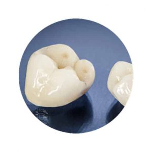
Tooth that got a root canal treatment or severely broken tooth would get a complete crown or bridge with the shape of the normal tooth. The dentist attaches the restoration with special cement for permanent gluing, after milling the broken tooth to a certain shape in order to hold the crown firmly in its place.
A Full crown on top of a shaped tooth
A completely missing tooth would require either a bridge construction or an implant + crown.
When a bridge is done, the two adjacent teeth are prepared to a stage-like shape and the middle crown is supported by the two external teeth. Alternatively, an implant and abutment can be placed, and the new crown is adjusted accordingly.
When broken or missing tooth occur in the anterior (front) teeth section, the restoration is mainly done from esthetical reason. Functional reasons are more likely when several or all teeth are missing.
How dental crown is made?
In case of crown or bridge covering broken teeth, the teeth must be reduced in size so that the crown or bridge will fit over it properly. In the next stage there are two options;
The conventional way is to use a tray with a silicon material impression, which the patient puts in mouth and bites. After a while the silicon material hardens and can be taken out, consisting the 3D shape of the relevant location. This impression is used later for creating another harder impression model cast of the positive shape to be used for measurements and scanning. The scanning information assist the technician to determine the shape of the new required tooth.
A Model Scanner
A more modern way is to use an intraoral digital scan of the prepared tooth in the mouth which makes the need to take impressions, redundant. The equipment required to perform these scans consists of a hand-held scanning tooth-brush-like stick that houses a miniature imaging system. This is connected to a hardware module that both powers the scanner and receives the digital generated image. This scanning file can be than used in a fabrication lab to eventually produce the crown.
Intraoral digital scanning
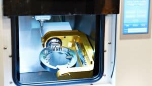
The fabrication lab uses the STL file to create in CAD (computer aided design) software the necessary shape of a crown to be mounted on top of the broken tooth or the missing tooth. When the file is ready, the same software turns the CAD file into a CAM (computer aided manufacturing) file to be transmitted to a dedicated 5 axis CNC machine.
In the process of Dental crown manufacturing there are different types of machines, from various manufacturers, such as: Amann Girrbach, Dentsply Sirona, Zirkonzahn and others, each one dictating the shape of the raw material, the dimension of the milling tools and the machining strategy, e.g. cutting speed, feeds, stock removals etc.
A zirconia disc during machining
The milling tools which are traditionally in use during dental crown manufacturing are made from tungsten carbide, capable of machining around 100 crowns (depending on size and shape).
Telcon Diamond Ltd is the first company to present PCD (polycrystalline Diamond) crown machining burs.
Since PCD is 5 times harder than Tungsten carbide, the PCD tools are much wear resistant, therefore life expectancy is 10-15 times more than the Tungsten carbide. In fact, 1500 machined crowns can be achieved on regular basis.
Another advantage is consistent high crown quality over time. While Tungsten carbide tools wear faster and lose their size (diameter) faster, deterioration of crown surface finish and dimensions is a fact. Inconsistent quality such as, mismatch, “wavy” surface and broken thin wall can be seen. The first and the last crowns are not within the same quality. With Telcon’s PCD tools, crown surface quality and dimensions are kept the same for much longer hours.
Telcon’s PCD crown milling burs are designed to be used in three machine platforms – Sirona Inlab MC X5, Zirkonzahn CAD/CAM M systems and Amann Girrbach ceramill mikro 5X.
After zirconia crowns are manufactured, they should get their final working hardness within a sintering furnace. This process may take between 2 – 8 hours, depending on the hardness levels the lab would like to achieve.
No machining whatsoever is done on the crowns in hard state and the crown is practically ready. If specific coloring is required, then it should be applied prior to sintering.
Telcon Diamond Ltd is the only company who suggest a revolutionary process of machining the zirconia also in the hard state, that is, skipping the sintering process, saving time and material (due to 20% shrinkage in sintering). This machining process is under research and is likely to become productive in the near future.
Want to test our dental milling tools? click blow to order the tools now:
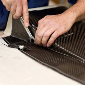
Composites materials are commonly consisting of two materials: the fibers and the bonding material. In the layup phase in production of the composites part, layers of composites cloth, are built one on top of the other, either manually or automated in a manufacturer specific fiber direction. These layers constructing the thickness of the final part, must be kept intact, unseparated. Damaged material will be weaker, with a potential probability of part failure. PCD drills are designed and manufactured to prevent this event in composite materials, where both the cutting edge and the PCD coating is radically improving tool life and wear resistance, Keeping the cutting edge sharper for longer period of time.
Machining of composites, with PCD tools or other tools, e.g. drilling, milling etc. might cause damage to the composite materials due to the nature of the cutting action and from various reasons, which we will address here.
Potential failure modes in machining of composites are:
Layer delamination.
Uncut fibers.
Uncut resin.
Spalling/splintering.
The most severe failure mode is layer delamination since it is more likely to occur, it has higher impact on material strength, and it is more difficult to fix.
Drilling operation in composites is widely use since composites parts are connected via riveting, therefore all holes are through holes and there are no threaded holes. Generally, the exit hole is more likely to suffer from delamination of layers when drilling in composite materials due to the tool movement direction and cutting forces applied on the lower layer of the material.
There are few factors which influence the probability of delamination to occur:
Drill geometry.
Drill substrate.
Cutting conditions and process.
Workpiece mounting fixture.
On this article – We will focus on the first two factors.
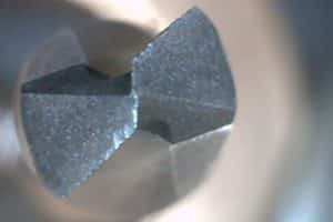
Drill geometry:
A drill with point angle for designed for metal (118 deg and higher) will likely to cause excessive forces on the drill exit, by tearing the last layers too aggressively and causing separation and delamination around the drilled hole.
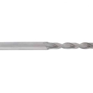
A PCD drill with 135deg point angle (for Aluminum)
A sharper point angle drill (like 90deg) will have better results while reducing exit forces. However, angle transition, between the point and the cylindrical portion of the drill creates another built up pressure to the last layers.
Telcon Diamond drills, designed for composites, offer 8 facets point geometry, or double point angle which is longer point structure. The second angle, closer to the drill diameter is quite steep, reducing exit forces. Of course, one must consider the space beneath the part to verify there is enough space for the longer point angle drills.
Drills can be used in CNC machines or manually. While drills presented above are for CNC or ADU (auto drilling unit) usage, drills for composites which are used manually have different shape.
Still, though, the point angle must be sharp, for two reasons, one as discussed before, to reduce cutting forces on drill exit, and the second relates to the manual operation itself. Sharper drill, requires less pressure from the operator, therefore applying less force on the material itself, avoiding delamination issues.
One difference we in manual drills, to CNC drills is the flute helix (spiral) angle. While in CNC, machine has fixed location and rigidity in action, in manual operation spiral drills are very difficult to use to maintain a clear cut, hole concentricity and good surface. Therefore, most of manual drills for composites have straight, or very low spiral flutes.
Telcon’s manual carbide drill/reamer double point angles
Drill substrate:
Composites are being cut cleaner when tool cutting edges are sharp. The removed material flowing on the edge of the tool gradually rounds it and makes it dull. Rounded edge applies more axial forces on the material, causing it to be pushed instead of being cut and sheared.
Therefore, the harder tool substrate is, the higher its wear resistance.
Worn out drill cutting edge
Most common composites drill is made from Tungsten carbide. On a scale of 1 to 10, carbide hardness is 2-3, while PCD or CVD coated is on a scale of 7-8.
It is clear, therefore, that diamond tools can last much longer than carbide tools on composites.
If one wants to consider the options, since diamond tools are more expensive than carbide tools, the right way to compare both is by calculating cost per hole. The added value in tool life of diamond tools compared to carbide tools in composites, is much larger than the price difference.
Telcon’s drills for composites, used in CNC operations, as shown above, are all made from PCD segments or CVD coating, in order to maintain hole quality for longer period. A combination of an efficient geometry with the highest quality substrate, brings better, long lasting drilling results.
This article will explain about the two major composites matrices which are in use in the industry and particularly in the aerospace.
Most composite raw materials are purchased ready to be used by the part manufacturers. There are two major composites resin groups, ready to be used, which require different manufacturing methods; Thermoset matrix and thermoplastic matrix composites.
Thermoplastic composites are usually heated and molded or pressed into a mold to receive their final shape, then cooled and to final part is shape. The process involves only heating and cooling. The process is rather short and reversible. Since heating must take place immediately for the impregnation process, most of thermoplastic composites process are automatically done, involving in-situ consolidation, either in compression molding, filament winding
Thermoset composites layers are laid one on top of the other manually or automatically to the final part width and then oven-cured under vacuum bag to generate chemical reaction which brings them to their final solidification stage and properties. The process is longer and non-reversible.
The table below shows major differences between the two composites types:
Thermoset Composites
Thermoplastic Composites
Generated during curing
(chemical change)
Generated by heating and cooling of the plastic matrix (physical change)
Non-reversible
Reversible
Easier to impregnate the fibers into the matrix in room temperature, Easier to process to final shape, thick to thin walls capabilities.
Impregnation can be done only during heating; therefore, reaching to final shape is more complex and costly.
Longer process cycle time due to Oven curing which takes few hours
Shorter process cycle time, no curing required, however, higher temperatures are required for the processing
Hard and rigid
Tougher and more flexible, therefore higher impact resistance
High fatigue strength
Lower Fatigue strength
Higher heat resistance
Lower heat resistance
Higher dimensional stability
Lower dimensional stability
Used mainly with continuous fibers
Used mainly with discontinuous fibers
Non-recyclable
Recyclable
Raw material must be stored in a specific environment and has limited shelf life
Regular storage conditions, unlimited shelf life
Cannot be welded, must be assembled with rivets and fasteners (adding the need for hole drilling and countersinking)
Under specific conditions, can be welded to other thermoplastic part
To date, in Aerospace applications, more than 95% of prepregs are thermoset.
The nature of thermoset Composites
Thermoset composites have been successfully manufactured for aerospace since the 1960’s, and the knowledge is vast and mature. In addition, highly investment has been put during these years to develop processes, materials, equipment, gigs, training and testing for implementing the thermoset composites in aerospace parts.
Major structures in the Boeing 787, the Airbus A350 and Lockheed Martin F35 almost exclusively thermoset composites. Structural airplane parts such as fuselage, wings, beams, tails and others are made from Thermoset composites.
In the automotive, sports cars, supercars and some mass production cars, like BMW i3, are using thermoset composites.
All the energy windmills blades are made from thermoset composites.
Thermoplastics composites, on the other hand, were firstly used by Airbus on the A340, A380 and later, also on the A350. Up until recently, thermoplastic composites on airplanes have been used only for smaller parts like clips or brackets. This is gradually changing as better materials and processes are being developed while thermoplastic composites are being used in bigger parts in components like the horizontal stabilizer of the Leonardo AW169 helicopter, the rudder and elevators on the empennage of the Gulfstream G650. Additional parts were developed such as the fixed wing leading edge, keel beams, interior components, engine pylons, access doors, aircraft flooring and a variety of molded interior parts.
In fact, thermoplastic composites offer number of important advantages over thermoset:
It has higher degrees of impact toughness. It does not require special storage conditions. It does not need to be cured in autoclave for many hours. Two or more parts can be welded together saving the use of rivet connection (drilling & countersinking). And, it is more ecological since it can be recycled.
Why you will need high quality tools?
There are disadvantages for thermoplastics, which hold back a greater usage of these materials. The main disadvantages: impregnation of fibers can be done only during heating; therefore, reaching to final shape is more complex and costly. In addition, it has lower dimension stability than thermoset composites and has lower heat resistance.
Due to the nature of aerospace industry working under stringent regulations, it would still take years of investment in research and testing until thermoplastic composites will conquer higher volume of usage as compared to thermoset composites.
Telcon Diamond has developed over the years PCD and CVD solutions for both thermoset and thermoplastics composites. While thermoplastic composites involve less drilling and countersinking, the milling (routing) operation of these materials can be challenging since these parts are more flexible and elastic, therefore milling is less stable and tool geometry must be designed accordingly.
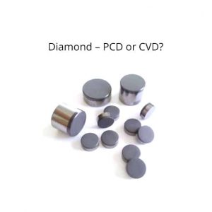
In this article, we’ll try clarifying and shedding more light on a dilemma confronted by many end users of cutting tools to machine composite materials, when they are required to decide which type of tool to use for their application. There are mainly two types of diamond cutting tools for composites: PCD tools, where the cutting edge is built from a PCD segment of a specific size and shape and CVD diamond coated tools, where the tool’s edge is completely built in a grinding operation and later coated with CVD diamond.
PCD
PCD (Poly – Crystalline – Diamond) is, unlike single crystalline diamond, produced synthetically by sintering together many (Poly) diamond particles, usually in the size of 2 to 30 microns of a meter, with a metal binder (usually Cobalt) at high temperature and high pressure. The rate is 90-95% diamond particles and the rest is Cobalt.
CVD Diamond
(Chemical Vapor Deposition) is a process of coating Nano diamond particles on a Tungsten carbide substrate applying a layer thickness of 6 to 16 microns of a meter. The tungsten carbide substrate has to contain low cobalt content, such as 6% an d has to go through specific surface treatment. The treatment reduces cobalt content in the outer layer, exposing the diamond edges, in order to create sufficient adhesion between the diamond coating and substrate.
In the table below, summarized is a comparison between the two types:
PCD is a composite diamond, 90-95% diamond powder + cobalt binder, therefore lower hardness than CVD. Around 6000 Vickers hardness.
CVD is 99% pure diamond, therefore hardness is the highest. Around 8500 Vickers hardness.
Wear resistance
Since PCD contains cobalt, the edge is more likely to wear faster, but that occurs until a certain edge radius is reached and remains constant for a longer period.
Since CVD is pure diamond coating, the wear resistance is higher, so edge radius is kept sharper for a longer period. However, when coating wears off, since the material beneath is tungsten carbide, edge sharpness deterioration is much faster.
Toughness
The cobalt metal binder in the PCD material adds to the strength of the material, as compared to the CVD diamond. Therefore it is likely to have better resistance to chipping in milling operations and in unstable machining conditions.
The almost pure diamond layer has lower elasticity and strength, therefore would be more likely to fracture and delaminate than the PCD.
Design
PCD tools in the form of wafer segment are limited in geometry to the segment shape. However, when a full nib PCD is used, there are no design limitations.
Since CVD tools are first shaped in a grinding operation, there are no geometry design limitations.
Trying to make this comparison practical, let’s discuss different applications in regard to these two diamond tools:
Milling operations involve interrupted cutting of the material, where each end mill tooth is engaged with the material and exiting it in one tool revolution. Each time the cutting edge enters the material, the “hammering” effect damages the cutting edge of the tool. Looking at the table above, PCD tools are more likely to withstand the “hammering” effect in milling. In CVD diamond coated tools, the CVD coating eventually delaminates and only the tungsten carbide substrate is left. In the PCD, even if some fracture occurs, the diamond is solid and therefore keeps the same characteristics. There is a concern, though, about geometry limitations with the PCD. For instance, when a particularly long flute length is required, or when specific tool geometry is required, e.g. porcupine router, the CVD diamond tool has an advantage.
In drilling operations, the cutting edge has constant contact with the material, unlike milling, therefore the cutting edge is less likely to chip or fracture. Taking that into account, with a combination of hardness and sharpness, CVD diamond drills perform better in regard to minimizing the delamination at the hole exit. This is a major concern in the drilling of composites in highly engineered parts, such as Aerospace. When delamination is the failure criteria, there is no doubt that CVD drills outperform PCD drills. However, when hole diameter is the failure criteria, then the PCD drill will “survive” longer than CVD drills. The reason for this is due to the fact that the CVD diamond is a coating. When it eventually delaminates from the tungsten carbide, edge wear accelerates rapidly. The PCD, on the other hand, as said, is a solid diamond. Wear development rate is almost constant. Another example where PCD may have an advantage is the drilling of stack material like CFRP/Al, where the exit hole is in the Aluminum. Delamination is a non-issue in this case, therefore PCD would be first choice, since it will hold longer and can also be reconditioned a few times. Another advantage of the CVD diamond drill would be design flexibility, while comparing to standard wafer drill, where PCD segment dictates geometry. On a Fullnib PCD drill, however, there is no geometry limitation and design flexibility is the same as in the CVD diamond drill as long as PCD nib height (which is limited) does not create other limitations.
While countersinking is considered a manual operation, the countersink body is made from steel, mainly due to the thread connection. Steel cannot be coated with CVD diamond; therefore, most countersinks in the market for composites are PCD. PCD segments are brazed to the steel body of the countersink. Full carbide countersinks which can be coated are rarely seen, due to the fact that grinding the thread on the tungsten carbide body is a complex task.
To Summarize:
The main purpose of this article is helping end users focusing on their goals in a given application. Knowing and understanding your goals, will assist in clarifying tool requirements and choosing the right tool to the application. As it was explained in the article, both PCD and CVD cutting tools have their pros and cons. None of them can fully replace the other. We were not discussing in this article other factors like tool cost, reconditioning, tool diameter limitations and more. Some of these factors will certainly influence our decisions and will be discussed in the following articles. Telcon offers both solutions of PCD and CVD diamond Drills, End Mills, Routers and countersinks for all your composites applications. Feel free to contact us for further information at [email protected].
Composite materials are synthetic materials that are made from two or more material components with different physical or chemical properties that, when combined, produce a material with different (usually better) characteristics than each of the individual components, composite materials are commonly designed to serve specific purpose and the attributes of the material are designed to serve this purpose, for example carbon fiber materials that are designed for light weight and High strength with high brittleness.
Composite materials are in use in various applications in Aerospace, Automotive, Energy, Sports, Construction and more.
The fundamental advantage of composite materials is higher strength to weight ratio, which brings added value in the aforementioned applications.
In most cases, composite materials are constructed from two main materials: fibers of strong material, such as Glass or Carbon and a polymer matrix material, such as epoxy, which bonds the fibers together in a certain shape.
The table below summarizes the majority of composite material options:
Fibers
Polymer Matrix (bond)
Carbon fiber
Epoxy
Glass fibers
Phenolic
Ceramic fibers
Polyimide
Polymer fibers (Kevlar, Polyethylene)
Poly-ether-ether-ketone (PEEK)
Tungsten fibers
The two most advanced composite materials in use are Carbon Fibers, also called CFRP (Carbon Fiber Reinforced Polymer) and Glass fibers, also called GFRP.
About the Common types of Composite materials
Mass production of glass strands was accidentally discovered in 1932 when Games Slayter, a researcher at Owens-Illinois, directed a jet of compressed air at a stream of molten glass and produced fibers.
It wasn’t until the late 1950’s that high tensile strength carbon fibers were discovered. Rayon became the first precursor used to create these modern fibers. Ultimately, it was replaced by more effective materials such as polyacrylonitrile (PAN).
Between the two, GFRP is lighter and stronger, however, more expensive, therefore in use mostly in Aerospace and in luxury and sports cars and professional sport equipment.
Manufacturing process of composite materials involves three main technologies; the manufacturing of the fiber, the manufacturing of the polymers and the manufacturing of the combined composite material itself.
The process for making carbon fibers, which is part chemical and part mechanical involves the use of a precursor (About 90% of the carbon fibers produced are made from polyacrylonitrile, PAN) which is drawn into long strands or fibers and then heated to a very high temperature without allowing it to come in contact with oxygen. Without oxygen, the fiber cannot burn. Instead, the high temperature causes the atoms in the fiber to vibrate violently until most of the non-carbon atoms are expelled. This process is called carbonization and leaves a fiber composed of long, tightly interlocked chains of carbon atoms with only a few non-carbon atoms remaining.
It’s all in the fiber materials
Fiber reinforced composite materials can be divided into two main categories normally referred to as short fiber-reinforced materials and continuous fiber-reinforced materials.
Continuous reinforced materials will often constitute a layered or laminated structure. The woven and continuous fiber styles are typically available in a variety of forms, being pre-impregnated with the given matrix (resin), dry, uni-directional tapes of various widths, plain weave, harness satins, braided, and stitched.
The short and long fibers are typically employed in compression molding and sheet molding operations. These come in the form of flakes, chips, and random mate (which can also be made from a continuous fiber laid in random fashion until the desired thickness of the ply / laminate is achieved).
In the next article we will discuss different manufacturing methods of composite materials, their pros and cons and their use in the industry.
Diamond is a solid form of the element carbon with its atoms arranged in a crystal structure called diamond cubic.
Why do we use it diamond
Typically, natural diamonds age for between 1 billion and 3.5 billion years. Most were formed at depths between 150 and 250 kilometers in the Earth’s mantle. Some have come from depths of as much as 800 kilometers under high pressure and temperatures, where carbon-containing fluids dissolved minerals and replaced them with diamonds. Much more recently (tens to hundreds of million years ago), they were carried to the surface in volcanic eruptions and deposited in igneous rocks known as kimberlites.
Diamonds have the highest hardness and thermal conductivity of any natural material.
See the diagram below which emphasizes the level of hardness of diamond in comparison to other materials. The material with the next level of hardness is CBN which is less than half as hard as the Diamond.
Why do we use it diamond
Hardness is a fundamental property of a material to resist a force applied causing it to deform. Another interpretation of the diamond hardness would be higher wear resistance. It can be easily understood that when diamond is in abrasive contact with another material, the diamond would remove much more stock from the other material, than would be removed from the diamond itself.
Clearly, due to higher hardness, diamond applications can be seen in the cutting tools industry. Diamonds are used in grinding wheels to grind hard metals, such as tungsten carbide or to cut and shape granite. Diamonds are being used as a cutting tool edge for the machining of non-ferrous abrasive materials, such as composite materials, hard ceramics, high silicone aluminum etc. Diamonds are also being used as a cutting edge in the road-header on excavating machines for roads, tunnels and mining.
Why do we use it diamond
The second advantage of the diamond as a cutting tool material is the thermal conductivity.
During machining, the cutting forces generate heat. The heat is distributed among 3 elements: the workpiece, the cutting tool and the removed material chips.
The high thermal conductivity of the diamond will ensure that large amounts of heat energy is dissipated in the tool itself and less to the workpiece. This protects the workpiece from thermal shock or deformation; this is mandatory, for instance, when machining carbon fiber reinforced plastic (CFRP). A higher heat level in the material might cause melting of the resin material while deteriorating the composite material’s mechanical properties.
Telcon has been manufacturing in-house cutting tools for more than 35 years and gained vast experience and expertise in the manufacture of Diamond PCD tools and solutions for various applications in the machining of composite materials. All cutting tool solutions (PCD drills, CVD drills, PCD end mills and CVD routers or PCD countersinks) are high quality and high performance, providing long tool life with non-delamination and non-bur issues.
What are the differences between real and synthetic diamonds
The main difference between real diamonds and synthetic diamonds is that, real diamonds are mined and synthetic diamonds are created in the laboratory.
Natural Diamonds are formed inside the earth mantle over millions of years at high temperatures and depth. Diamond is made of carbon and has a crystal structure.
Synthetic diamonds also known as “lab grown”, are not mined but are created in the laboratory. These diamonds are made from carbon and even have the same physical properties and chemical composition as natural diamonds. They are made by HPHT (High-Pressure High-temperature) or through commonly used CVD (Chemical Vapor deposition). They are designed to look like real diamonds and have the same characteristics.
The uses of Synthetic diamonds
Synthetic diamonds are lower priced compared to natural diamonds and therefore are used in many industrial applications.
One of these applications is PCD – Poly Crystalline Diamond. PCD is a synthetic diamond produced by sintering together selected diamond particles with a metal matrix at high temperature and high pressure.
The polycrystalline form is ‘isotropic’ – exhibiting uniform properties in all directions. The varying orientation of the constituent micron-sized synthetic diamond grains also provides a greater resistance to cleavage and PCD is therefore, a stronger material. PCD can be machined in electric-discharge machining (EDM) process due to conductive metal content, mostly cobalt. Still, diamond content of the PCD is 90-95%.
What we do with synthetic diamonds
In Telcon, we machine most of the PCD tools in Erosion (EDM) technology, which is applied in wire-cut EDM and disc shape EDM. Among our diamond cutting tools solutions, you can find: diamond drill bits, diamond countersinks and diamond end-mills. In each of these tool categories, you can find both PCD and CVD solutions. For example, you may find PCD drills and CVD drills, PCD end-mills and CVD end-mills for various applications.
Telcon Diamond Ltd. is a world leading manufacturer of Diamond PCD and CVD cutting tools for the machining of composite materials: CFRP, GFRP, MMC, CMC and hard ceramics. TELCON produces a wide range of tools used by many of the world’s leaders in the field including Boeing, Airbus, Lockheed-Martin, Spirit, ATK, Embraer, Denel, ELBIT and IAI. Telcon’s tools include: PCD tipped Drills, CVD diamond drills, Carbide drills, PCD Countersinks, Carbide tipped Countersinks, PCD tipped End Mills and CVD diamond End Mills and Carbide End Mills.
TELCON possesses the most advanced Grinding, and EDM machines and state of the art Quality control equipment. TELCON’s vacuum brazing equipment is highly controlled to ensure repeatability and reproducibility of brazing operation. TELCON uses world class PCD and carbide grades and CVD coatings. In addition to tools manufacturing, Telcon operating reconditioning services for PCD and carbide tools.